
Building My Own Tool Scanner — Part 1: There Has to Be a Better Way
Like a lot of my projects, this one started because I couldn't be bothered doing something the long way.
I wanted to organise my toolbox using Gridfinity.
I've got several 3D printers, I use CAD regularly, and designing custom inserts isn't particularly difficult. Take some measurements, recreate the tool profile, add some clearance, create the pocket, print it and see if it fits.
For one tool, that's fine.
For an entire toolbox?
Absolutely not.
The original problem
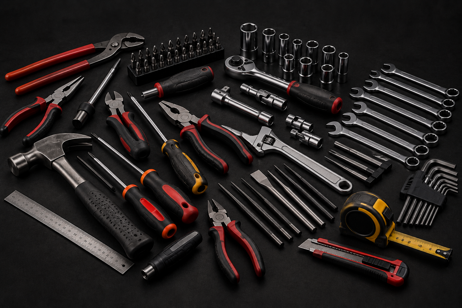
Making a custom insert for a tool sounds simple enough until you actually start doing it.
Take a pair of pliers as an example.
I can measure the overall length and width easily enough, but that doesn't give me the shape of the handles. So now I'm taking additional measurements at different positions, recreating curves, measuring the head, adding radii, checking clearances and trying to reproduce something that was never designed around convenient CAD geometry in the first place.
Then there are ratchets, cutters, adjustable spanners and all the other oddly shaped tools.
And after all of that, you still have to print it.
If the clearance is wrong or you've measured something slightly incorrectly, it's back into CAD, change the model and print it again.
None of this is particularly difficult.
It's just tedious.
And tedious, repetitive processes tend to make me wonder whether there's a better way of doing them.
Why am I measuring the tool at all?
That was the question that eventually started this project.
I'm holding the physical object I want to create a pocket for.
Its outline already exists.
So why am I sitting there with a pair of calipers trying to recreate it?
Why can't I just scan the bloody thing?
The basic idea seemed straightforward.
Put a camera above a flat surface.
Place the tool underneath it.
Take a photograph.
Find the outline of the tool.
Convert that outline into real-world dimensions.
Use it to create the pocket.
Done.
Or at least, that was the theory.
I tried a few of the online AI tool scanners with varying degrees of success.
Varying degrees of success was not good enough.
The first concept
I wasn't trying to build a 3D scanner.
That distinction became quite important later.
I don't need to reproduce the complete geometry of the tool.
For most of the inserts I wanted to make, I primarily needed an accurate 2D silhouette.
The depth of the pocket can be specified separately.
That simplifies the problem enormously.
Instead of trying to determine the complete 3D shape of a ratchet, the scanner only needs to answer:
Where is the outside edge of this object, and where is that edge in real-world millimetres?
Once I have that, I have something I can potentially use as cutting geometry.
So the basic concept became:
Physical tool → Camera → Image processing → 1:1 profile → CAD → Gridfinity insert
At least on paper, that looked suspiciously easy.
The hardware
I also didn't want this to become a project where the solution involved throwing expensive hardware at the problem.
The camera was a Logitech C920 webcam.
Nothing exotic.
It's a normal 1920 × 1080 webcam that I already had.
Fix it above the scanning area, point it straight down and start experimenting.
The eventual aim was to have a dedicated scanning station where I could walk up, put a tool down, enter its name and scan it.
No rulers.
No calipers.
No tracing.
No manually recreating a pair of pliers using twenty different measurements.
Just:
Put tool down → Scan → Get profile.
That was the goal.
The physical frame was built largely from parts I already had lying around. I repurposed components from an old Anycubic Kossel and an Anycubic Zero, using the aluminium extrusion and hardware to build the scanner structure rather than designing everything around new parts.
It suited the project perfectly: take redundant hardware, give it a completely different purpose, and only design or print the parts I actually needed.
And then reality arrived
The first images actually looked pretty promising.
The camera could clearly see the tool.
Finding its approximate outline wasn't particularly difficult.
And because the camera was mounted directly above the work area, I initially thought converting that outline into something dimensionally useful would be fairly straightforward.
There was, however, one fairly significant problem.
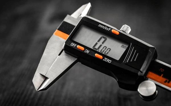
A camera image isn't a technical drawing.
Perspective changes dimensions.
The camera isn't necessarily perfectly perpendicular to the surface.
And, more importantly, the lens itself distorts the image.
A straight line in the real world isn't guaranteed to behave exactly how you expect when measured in pixels.
If I only wanted a picture of the tool, none of that would matter.
But I didn't want a picture.
I wanted to eventually cut a pocket from that image, print it, and put the original physical tool into it.
Being a few millimetres out wasn't going to cut it.
So before I could really start working on the tool detection itself, I needed some way of teaching the scanner what it was actually looking at.
My first solution?
Two L-shaped markers.
One in each corner.
Known dimensions.
Correct the perspective from those and surely everything would line up.
Simple.
...
Yeah.
That didn't quite work. 😂