
Building My Own Tool Scanner — Part 1: There Has to Be a Better Way
I wanted to organise my toolbox.
That was it. That was the grand plan.
I've got 3D printers, I use CAD, and Gridfinity looked like a decent way of finally giving everything its own place. Instead of tools rattling around in drawers, I'd print inserts shaped to fit them. Nice and tidy.
The problem wasn't printing the inserts. It was everything I had to do before printing them.
For a simple rectangular tool, fair enough. Measure the length and width, draw a shape, add a bit of clearance and make the pocket. Job done.
Now try that with a pair of pliers.
You've got the jaws, the pivot, two handles that aren't straight, and curves that change along their length. You can measure the overall dimensions easily enough, but that doesn't tell you the shape of the tool. To make a pocket that actually follows it, you're either taking a load more measurements or tracing the outline manually in CAD.
For one tool? Not a massive issue.
For a toolbox full of them? That's a pain in the arse.
And the daft thing is, the shape I'm spending all that time trying to recreate is already sitting on the bench in front of me.
Why am I drawing something that already exists?
That was the question that started Titan Scanner.
If I could take a photograph of a tool from above, surely I could get its outline from that photograph. Then I could bring the outline into CAD, add the clearance I wanted and use it to make the Gridfinity insert.
Put the tool down. Take the picture. Get a properly sized outline. Make the insert.
Sounds straightforward, doesn't it? 😂
There was one important distinction from the beginning: I wasn't trying to make a full 3D scanner.
I don't need a complete digital model of a ratchet just to give it somewhere to sit. Most of the time I need its footprint. How deep the pocket should be, where to put finger access, and how much clearance to allow are separate design decisions.
That makes the problem a lot more manageable. The camera doesn't need to know what a ratchet is. It doesn't need to recognise the make or model, or work out what the tool does. It just needs to tell me where the edge is and, crucially, where that edge is in millimetres.
I'd already tried online AI-based tool scanners, with mixed results. Some of the outlines looked promising, but looking right and being right aren't the same thing. A convincing picture is no use if the resulting pocket doesn't fit the tool.
I wanted something I could test, measure and improve myself.
Start with what I've already got
The first camera was a Logitech C920 webcam, running at 1920 × 1080. Nothing exotic. I also had aluminium extrusion and parts left over from old Anycubic Kossel and Anycubic Zero printers, so those could be repurposed for the frame.
That suited me fine. I wasn't about to start buying expensive machine-vision hardware before finding out whether the basic idea worked.
The setup needed to hold a camera above a scanning area, keep everything reasonably stable, and give me an image I could process. Eventually I wanted a dedicated station where I could name a scan, capture it and get a useful outline without sitting there tracing curves by hand.
The first bit was encouraging.
I could put a tool under the camera, take a photograph and find something that looked like its outline. That's a pretty good feeling when you're testing an idea that, until recently, was just a way of avoiding an annoying CAD job.
But I hadn't really solved the important problem yet.
I'd found an outline in pixels.
I needed an outline in millimetres.
And that is where this stopped being quite so simple.
A camera doesn't measure things just because you ask nicely
Imagine taking a photograph of a ruler. You can count how many pixels cover 100 mm and work out a scale. Easy.
Except that only really helps if the scale stays the same everywhere you put the ruler.
With a camera, you've got perspective to deal with. The camera might not be perfectly square to the scanning bed. The lens itself can distort the image, particularly towards the edges. Something that measures a certain number of pixels in the centre might cover a different number of pixels when you move it towards a corner.
The physical object hasn't changed. Only its position in the image has.
That's a fairly serious problem when the whole point is to produce an insert that fits the actual object.
My first attempt at calibration used two L-shaped references with known geometry. The idea was to detect those references, use them to correct the perspective and turn the camera image into a properly aligned view of the scanning area.
And, visually, that could look pretty convincing.
The picture could be straightened up. Measurements close to the references could look reasonable. If I'd only checked those areas, I might have convinced myself it was working better than it actually was.
But move the object elsewhere and the measurement could change.
That's not a small cosmetic issue. It means the mapping from the photograph to the real world isn't describing the whole area properly.
I didn't need a photograph that looked square. I needed to know that 50 mm was 50 mm whether the tool was in the middle, at the top, or over towards a corner.
So, more reference points then
Two L-shaped references weren't giving me enough information about what was happening across the bed.
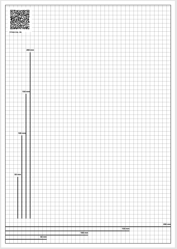
The next approach was a printed grid with intersections spaced 5 mm apart.
Rather than trying to correct the whole image from a couple of reference shapes, I could use known positions spread throughout the scanning area. The software would have far more information about how the camera was seeing different parts of the bed.
It also meant I could start treating calibration as something that needed to be tested, not just something that made the image look better.
Could the software find the intersections? Could it map them to their known positions? Would that mapping hold up when checked against measurements that hadn't simply been used to build it?
Those questions became much more important than whether the image looked neat on screen.
The early 5 mm grid was a genuine step forward in how I approached the problem. It wasn't the final calibration target, and I didn't know at the time how much further the calibration work would go. But it changed the way I was thinking about the scanner.
I wasn't just taking a picture and tracing a shape any more. I was trying to build a measurement system.
There's also a gap in the surviving history worth being clear about. The earliest calibration-target document I still have is from late August 2026. That doesn't mean I woke up that morning and invented Titan. It means that's one of the earliest points I can firmly anchor with a surviving document.
I'd rather say that than make up a tidy start date.
And then there's the computer running it...
At this stage I had the basic idea, a webcam, a repurposed frame and a calibration approach that was becoming more serious by the day.
I also wanted the scanner to run as its own little machine rather than depend on me doing everything manually at a desk.
Which meant moving the setup between computers.
And if there's one thing I've learned from engineering, it's that something working on one setup doesn't guarantee it'll behave itself when you move it to another.
The move from the MicroPC to a Raspberry Pi was about to prove that point rather nicely.
All of this because I wanted to stop measuring pliers and drawing them in CAD.
Next: Part 2 — Calibrating the Bloody Thing — Including the Tests